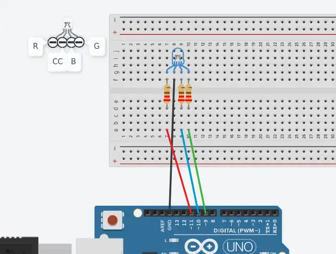
This project, although simple, contains several elements essential for working with Arduino and in general with microcontrollers. In addition to working with the RGB diode, the project involves using the analogWrite function to work with (certain) digital pins. Using this function implies the use of PWM signals, and also includes usage of user functions.
Project task: Traffic light simulation using an RGB LED
The project represents a simulation of traffic lights using one RGB LED Module. So it is not a classic traffic light with three separate lights. The sequence in which the lights change is as follows:
- The red light is on for 8 seconds;
- Then the yellow light turns on for 2 seconds;
- Then steady green for 7 seconds;
- The green light flashes for the next 3 seconds;
- It turns yellow again for 2 seconds, after which the sequence repeats.

An RGB diode is exactly the same as a classic LED, with the difference that it has four pins. One of these pins represents the common cathode, while the remaining three represent the anodes of the red, green, and blue diodes. You can see the construction in the picture. It can also be said that three diodes are packed in one body. Applying a voltage of logic 1 turns on a certain diode, that is, applying a PWM signal to the pin, the diode lights up with a certain intensity. This property allows the diode to glow in any color from the visible spectrum.
Code and explaination
The AnalogWrite function allows controlling the voltage on digital pins that can work with PWM signals. These are digital pins 3, 5, 6, 9, 10 and 11. There are two arguments that this function has. One is the digital pin on which the PWM signal is generated, and the other is the voltage level, which is represented by values from 0 to 255. The absence of voltage is represented by 0, while the maximum 5V is represented by the value 255.
The program is written using a single user function that has three arguments, each representing a voltage level for a red, green, and blue diode ranging from 0 to 255. It has no return value. Its purpose is simply to turn certain diodes on/off to emit red, yellow and green light. It is clear that only two diodes are used in this project, red and green. Blue, although not in use, is connected to the circuit.
The constants that are defined in the program are the pins to which the R, G and B pin RGB diodes are connected. In this case they are pins 9, 10 and 11.
The configuration function only defines the output modes of operation of these pins and serial communication is enabled because when each of the lights is turned on, a corresponding message is printed in the serial monitor. For example. If the red diode is on, the message “Red” is printed.
In the loop part, the diodes are continuously switched on and off in a defined sequence!
