Measuring the distance between two objects is important when talking about the organization and planning of space. This project makes it possible to do it in a simple, easy and relatively inexpensive way using an Arduino and an ultrasonic sensor HC-SR04. The only limitation imposed by the application of this sensor is the maximum range of 4m. For the needs of a hobby project in the household, it can get the job done, and quite well.
Ultrasonic ranging device task specifications
The circuit and program should solve the following problems (placing fence posts at a certain distance):
- Distance measurement and distance display in Serial Monitor.
- The distance of the object from the sensor should be expressed in centimeters.
- Measure every 300 ms.
- In addition to printing the distance, it is necessary to control the operation of the LEDs
- If the distance is less than 20 centimeters, it is necessary to turn on the red LED,
- If the distance is less than the set threshold by 2 cm or more, it is necessary to turn on the yellow LED that is to the left of the green one.
- If the distance is greater than the set threshold by 2 cm or more, it is necessary to turn on the yellow LED that is to the right of the green one.
- If the distance is equal to the set threshold of +/- 2 cm, the green diode should light up
- Only one diode should be on at a time.
Analysis and recommendations for the project
Initial and special conditions of the task:
- The measurement results must be expressed in centimeters and sent to the serial monitor
- The measurement is performed every 300ms
- Only one LED lights up at any time
Solving this problem can be divided into three simpler subtasks. Subtasks form an independent entity and are stored into separate functions, which makes the code more readable, better organized and shorter. The subtasks are:
- Distance measurement
- Data display in serial monitor and
- Control of diode operation
Ultrasonic sensor HC-SR04
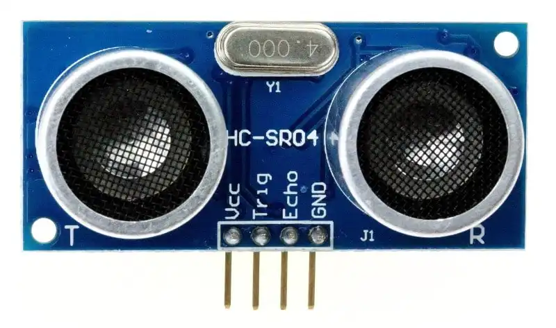
| # | Pin | Purpose | I/O |
| 1 | Vcc | Power +5V | – |
| 2 | Trig | Initiate measurement | In |
| 3 | Echo | An impulse whose duration represents the distance | O |
| 4 | GND | Ground | – |
Principle of sensor HC-SR04 operation

Electrical scheme and wiring diagram
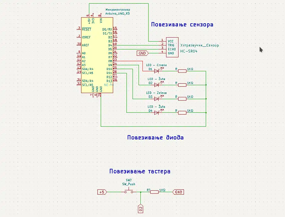
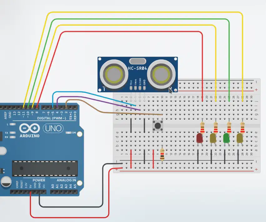
Necessary components for the circuit
The electric circuit consists of:
- microcontroller (MCU),
- ultrasonic sensor HC-SR04
- push button
- 4 LEDs (1 red, 2 yellow, 1 green)
- other necessary components for the circuit implementation.
Video tutorial of ultrasonic sensor HC-SR04
The program – sketch
Sketch (program) explained
Definition section
The ultrasonic sensor is connected to the Arduino board on pins 4 (Echo pin of the sensor) and 5 (Trigg pin of the sensor).
The diodes are connected to the digital pins of the Arduino, namely 8, 9, 10 and 11. These values are placed in an array. This definition is convenient for two reasons. Less typing in defining the mode of operation of the pins to which the diodes are connected and the function to turn on the diodes is simpler to do if array is used.
The button is connected to digital pin number 2 (it has the ability to work with interrupts).
The variable razdaljina is of real type that stores information about the distance of the object to which we direct the sensor.
The variable daljinaDoSusednogStuba stores information about the desired distance at which the posts are placed.
And at the end of the definition part, there is a variable prag that is used in the part of deciding which diode to turn on, and it is calculated in relation to the measured length and the desired distance at which the pillars are placed.
Setup section
In a for loop, the pins to which the diodes are connected are set to operate in output mode. Then triggPin is also set as an output. The pins to which the button and echoPin are connected work in the input mode, because certain information from the outside world is expected on these pins that affect the operation of the program. Finally, communication with the computer at a speed of 9600 baud was initiated.
Loop section
In the loop section at the beginning, the result of the izvrsiMerenje() function is placed in the razdaljina variable. This function is the first subtask that the program executes and its result is the distance to the object.
This is followed by a call to the prikaziRezultateMerenja function, which displays the result of the previous measurement on the serial monitor.
Information about the deviation from the desired distance at which the next pillar is placed is stored in the prag variable . Based on this deviation (tolerance), a specific diode is switched on. If the distance is less than 20 centimeters, the red diode will be turned on, whose index in the array is 0. In this case, it is turned on by calling the ukljuciDiodu function and passing the index 0. If the distance is greater than 20 centimeters, and the threshold is 2 or more centimeters less than of the desired distance, the yellow diode (to the left of the green) whose index in the array is 1 is turned on, or if the threshold is 2 or more centimeters greater than the desired distance, the yellow diode (to the right of the green) whose index is 3 is turned on. If the threshold is 2 centimeters or smaller, a glowing green diode (green diode index is 2).
Function – izvrsiMerenje
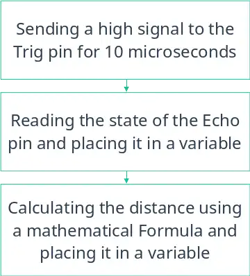
This function has a return value of type real. Its purpose is to control the operation of the ultrasonic sensor. Work management is done in three steps. The first is to generate a pulse and send it to the Trigg pin to start measuring the distance with the sensor. The second step is to read the pulse duration on the Echo pin which is needed to calculate the distance using the following formula:
daljina = trajanjeSignala * 0.034 / 2;,
Function – prikaziRezultateMerenja
The descriptive name illustrates very well what the purpose of this function is. Displays the measurement result in a specific format. This function is a second subtask.
Function – ukljuciDiodu
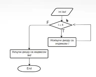
It remains to turn on a certain diode after the logic control defined in the loop section. That’s why this function has one argument (parameter) of integer type that represents the index of the diode to be turned on. Red has index 0 (the first element of the array), yellow has index 1, green 2 and second yellow has index 3. In a for loop, all diodes are first turned off to ensure that the diodes are off, before turning on a 1 with the passed index. The function has no return value.