At first glance, with the Arduino UNO microcontroller (μcontroller) it can be concluded that the number of digital pins is insufficient for a more serious project. The Arduino Mega offers 54 digital pins, so you can consider purchasing such a microcontroller. Another solution that allows you to increase the number of pins is to use shift registers. In this case, we are talking about the shift register 74HC595. How this is achieved, how a scroll register works and how to use it with an Arduino UNO controller is the topic of this video tutorial and text.
Video tutorial
How the shift register works – 74HC595
74HC595 shift register works on the principle of serial input and parallel output. This practically means that the data from the microcontroller is received bit by bit, while at the output the data is sent in parallel via 8 parallel pins. We can increase the output pins by 8 using a single chip. It is possible to connect several such shift registers by connecting pin Q7 to the DATA pin of the next shift register.
Pinout

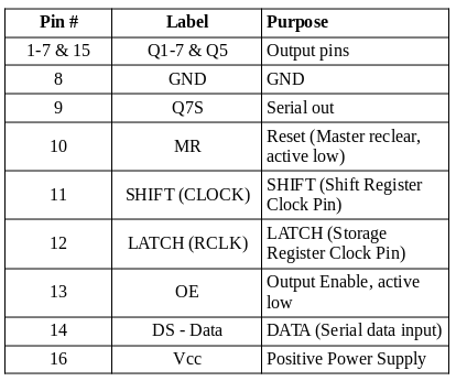
DS (DATA) – data is sent to the integrated circuit by pulses of high and low voltages with syncrhonization of clock signal (CLOCK).
CLOCK – it is a consistent high and low signal with a fixed frequency that acts as a data shifter for registers.
LATCH (RCLK) – refreshes the output from the integrated circuit even if data reception is still in progress. It will not display the output as long as the state of this pin is low.
Project description
The task of this project is to create a binary counter using LEDs (8 of them are needed for the project) with the help of a shift register. The binary counter is realized by means of a shift register in order to reduce the number of used digital pins of the Arduino UNO μcontroller, ie to increase the number of available pins of the μcontroller. The primary goal is to understand the principles of operation and how to use the shift register!
Required components
- LED’s (8. pcs)
- Resistors 220Ω (8 pcs)
- Shift register 74HC595
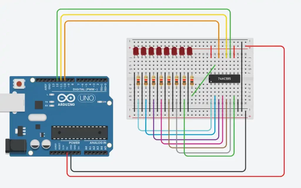
Electrical scheme
Sketch
// HC595
int CLOCK = 12;
int LATCH = 11;
int DATA = 10;
int counter = 1;

//podesavanje pinova kao izlaznih kako bi se kontrolisao registar
//setting pins as output to control the register
void setup(){
  pinMode(LATCH, OUTPUT);
  pinMode(CLOCK, OUTPUT);
  pinMode(DATA, OUTPUT);
}

void loop() {
  digitalWrite(LATCH, LOW);
  shiftOut(DATA, CLOCK, MSBFIRST, counter);
  digitalWrite(LATCH, HIGH);
  delay(500);
  counter++;
  if (counter >= 256) counter=1;
}
Sketch explanation
Definition section
The variables CLOCK, LATCH and DATA are defined with values 12, 11 and 10 (respectively). The names of the variables represent the pins on the integrated circuit to which the Arduino UNO will be connected, and their values represent the digital pins of the Arduino. The counter variable represents a counter whose initial value is 1.
Setup section
The CLOCK, LATCH, and DATA pins (12, 11, and 10) are defined as the output pins used to control the shift register itself. CLOCK represents the clock pin of the register, LATCH is the pin which (when active) displays the data stored in the register on the output pins. The DATA pin is the one with which we send data bit by bit and place it in the register.s
Loop section
digitalWrite(LATCH, LOW);
the LATCH pin (11) is set to logic 0, which turns off the output pins of the register, so there is no signal at the output;
shiftOut(DATA, CLOCK, MSBFIRST, counter);
This function writes one bit from the DATA pin (10) to the shift register with the clock CLOCK (12) in the order defined by the third parameter MSBFIRST, while the last parameter is the data that is written to the register – counter.
digitalWrite(LATCH, HIGH);
the LATCH pin (11) is placed on logic 1, allowing data to be displayed on the output pins of the register;
counter++;
the counter value increases
if (counter >= 256) counter=1;
if the value of the counter is greater than or equal to 256, then its value is set to 1 (the counter starts counting from the number 1 again).
Еxplanation of the shiftOut function
Transmits 1 byte of data bit by bit. The cycle begins from either the most or least significant bit. After each CLOCK trigger, 1 bit of data is written to the DATA pin.
Syntax: shiftOut(dataPin, clockPin, bitOrder, value)
Parameters:
dataPin – pin to which each bit is sent (allowed data type int)
clockPin – the pin to toggle once the dataPin has been set to the correct value. Allowed data types: int.
bitOrder – which order to shift out the bits; either MSBFIRST or LSBFIRST. (Most Significant Bit First, or, Least Significant Bit First).
value – the data to shift out. Allowed data types: byte.
Return value – None