Some time ago, I started to discover a new area in programming and electronics, it’s about the Internet of Things, a little more precisely about microprocessors and microcontrollers. As I announced in the first text on the blog one of my target areas is Arduino and it’s time for the first post! This text is different from the others, this time in addition to the text, video material for the first project is included, something like “Hello world!” – flashing LED. I follow trends a bit, or at least try, but I definitely enjoy doing this!
Hello World Arduino!
The first contact with Arduino was thanks to Trle, a colleague from the University, a friend, a person to whom I expelled people from his birthday with my current godfather. I wouldn’t want to start that story now, but it was spontaneous and not intentional! He showed me a couple of things he was doing, the equipment he was working with, so I quickly came into possession of a similar set myself.
Since then, I have been playing with RFID technology and making copies of tags for building entrances and similarly. At first, as is usually the case with me, it happened that I fried the reader’s sensor, but that’s how it’s learned.
Programming language C++
What particularly excites me, and that is that the Arduino is programmed with the programming language “C ++”, it is possible to use the classic “C”. They say on the Net it provides better control and more options. Now I will say that “C” is my old love! I use the word love, because when I started working in “C”, I knew that I would not have the opportunity to use it practically. However, I seem to have been wrong. On the other hand, a good knowledge of “C” made it easier for me to get to know the languages based on it, primarily PHP and JavaScript.
Flashing LED – Arduino project
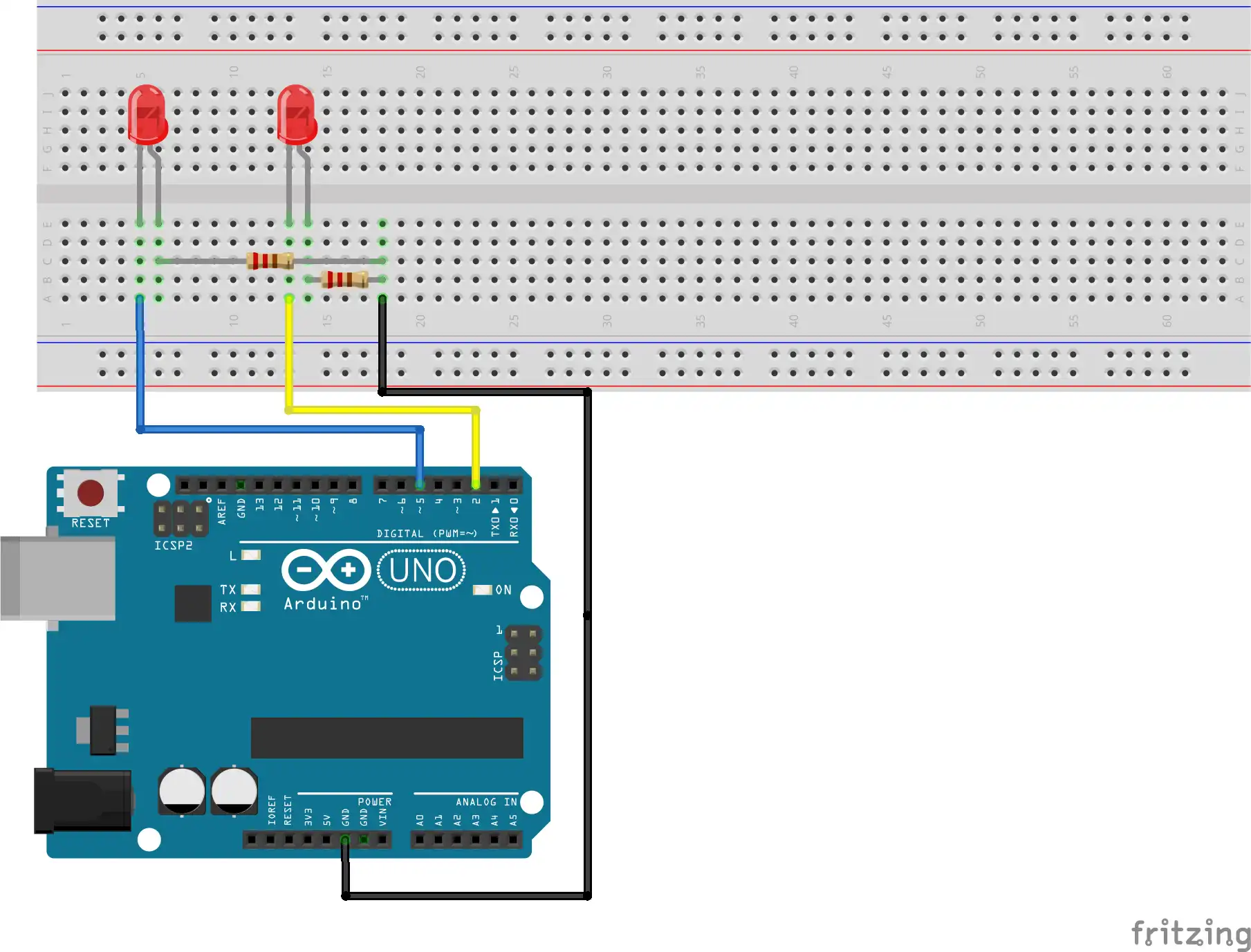
Let me go back to the Arduino and this basic project, the first text in the field, the first video. It is a basic, beginner project that aims to get acquainted with the pins of the Arduino, how they are used as outputs to control the operation of the electrical circuit. In this case, this control is reduced to alternating on and off LEDs in a certain time interval.
Required components
For such a simple project, few components are needed, in this case two LED diodes. Color is irrelevant to this story. Resistors, one for each diode. They serve to protect diodes from overvoltage. In this case, the resistance values are 220Ω. Why? There is also mathematics based on Ohm’s law and the possibilities of Arduino.
Ohm’s law and the possibilities of Arduino
Starting with the Arduino, the practical rule says that the safe current value for an Arduino UNO per pin is 14mA (this value implies the same current on all pins; if we are talking about current on only one pin, the value increases to 40mA). We have the value of current, we know the value of the output voltage on the pin – 5V and we know that the voltage on the directly polarized diode is 2V (value taken from the literature).
The LED and the resistor connected in series must together give the value of the supply voltage they receive from the Arduino pin. From here we can see that the voltage that develops on the resistor is 3V and by applying Ohm’s law we come to a resistance value of 214Ω. Of course, the standard values for resistors are 200 and 220Ω. We will take a higher value, of course. This value will slightly reduce the current through the diode (compared to those of 14mA), but it certainly does not interfere with the operation of the circuit.
Circuit diagram
Sketch
#define led1 2
#define led2 5
int state=HIGH;

void setup() {
  pinMode(led1, OUTPUT);
  pinMode(led2, OUTPUT);
}

void loop() {
  digitalWrite(led1, state);
  digitalWrite(led2, !state);
  delay(1000);
  state=!state;
}
Sketch explanation
In the first three rows of the sketch, we define two constants led1 with value of 2 and led2 with value of 5 and one integer variable state having value HIGH. A HIGH value indicates that the output of the Arduino pin is at the supply voltage value (5V or 3.3V).
In the configuration function, we define how the Arduino pins work, as inputs or outputs. We achieve this by using the pinMode function which receives two arguments. The first is the value, perhaps better called the name, of the pin we are working with, and the second is the pin mode, input / output using the INPUT / OUTPUT value.
The loop function, one that repeats until the Arduino power is cut off, alternately turns the LEDs on and off using the digitalWrite function, which also has two arguments. The first, as with the previous function, defines the pin we are working with, and the second sets the voltage value on the pin to a high or low value, ie HIGH / LOW. Initially, the value of the state will be HIGH for led1 and LOW for led2.
After a delay of 1000 milliseconds, determined by the delay(1000) function, the value of the variable state changes to LOW (because it is the opposite value of HIGH) by the negation operator – “!”.
The negation operator was also used with the digitalWrite function to provide the opposite value for the state and thus allow the LEDs to alternately turn on and off. In a function call, using the negation operator does not change the value of the state.
Conclusion
One very simple project, and so much writing. Fortunately, I managed to fit everything written in 1.30 minutes of video material and show everything that needs to be done for the circuit to work, of course there is no lack of explanation.